


Possible Problems Encountered in Power Supply Research and Development (2)
Question 10
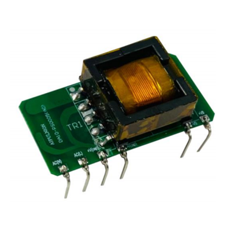
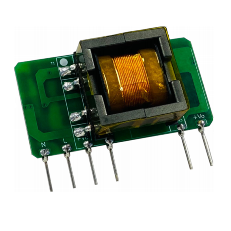
What kind of transformer is the most suitable? What does the transformer determine and what does it affect?
Designing the transformer is one of the core points of various topologies. The quality of the transformer design affects all aspects of the power supply. Some cannot work, some are not efficient, some have EMC difficulties, some have temperature rises, and some have extreme conditions. It will be saturated, and some safety regulations cannot be passed. It is necessary to consider various factors to design the transformer.
Where to start when designing a transformer? Generally speaking, the size of the magnetic core is selected based on the power. Experienced people can refer to the ones they have designed. Those who are inexperienced can only calculate according to the AP algorithm. Of course, there must be a certain margin. Finally, experiments can be used to test the quality of the design. .
Generally, the recommended low-power flybacks are EE type, EF type, EI type, and ER type. Medium and high-power PQ types are more commonly used. There are also differences in each person's habits and the platforms of different companies. The power is very large. Yes, if there is no suitable magnetic core, it can be done by tying the primary side of the transformer in series and paralleling the secondary side.
Different topologies have different requirements for transformers, such as flyback. What needs to be considered is in what mode it needs to work and how to adjust the inductance appropriately. Especially for multi-channel outputs, we must pay attention to the load regulation rate to meet the requirements, and the coupling effect should be good, such as using parallel winding, even winding, and increasing the number of secondary turns as much as possible. The withstand voltage of the MOS tube determines the turns ratio. How to choose the appropriate duty cycle and how much Bmax to choose (usually less than 0.35, of course 0.3 is better, and the saturation will not be too serious even if the short circuit is short). Some need to add shielding to rectify EMC. The original Generally, 2 layers of secondary side shielding are added, and 1 layer of outer shielding is enough.
High-power transformers generally pay more attention to losses, which require a balance between copper losses and magnetic losses. Natural air-cooling must also be taken into consideration. The appropriate current density is appropriate. For slightly larger powers (greater than 150W), the general current density should be relatively small ( 3.5-4.5), small power (5.0-7.0).
It is also important to know what safety regulations the power supply has passed, whether the retaining wall is sufficient, and whether the inter-layer tape is properly installed. It cannot be ignored. Once certification is required, changing the voltage regulator will also affect the progress.
Question 11
Do we really need to be obsessed with design tools and rely on simulation?
Power supply design tools are mainly used in the following aspects: 1. Select magnetic core and design transformer 2. Loop simulation design 3. Main power topology simulation 4. Analog circuit simulation 5. Thermal simulation (for high power) 6. Calculation tools (calculation book) and so on.
For newcomers, my advice is to use fewer tools, do more calculations, and control the design process by yourself, because tools are made by people, and different people have different design habits. You cannot use a fixed design model to design different power supplies.
Some simulations can be combined with design: for example, it is difficult to directly meet the design requirements after the loop is designed. Simulation can be well verified before testing, but simulation is not exactly the same as testing, at least not too far away.
It is also necessary to be proficient in using Mathcad and Saber, but we need to understand many aspects of the principles. We only need to use the tools as calculators, which is faster, more convenient and more efficient to meet our design. If we want to rely solely on tools to design power supplies, there is no doubt that This is a huge misunderstanding.
Question 12
When judging the quality of a power strip LAYOUT, what are the things that can be discovered immediately?
What kind of PCB is a good PCB? It must meet at least one of the following aspects: 1. Little interference in electrical performance, reasonable routing of key signal lines and bottom lines, and stable performance in all aspects (provided there are no defects in the circuit). 2. It is good for EMC, has low radiation, and the loop is reasonable. 3. Meet safety regulations, and the safety distance meets requirements. 4. Meet the process, mass production producibility, and reduce production costs. 5. Beautiful, the layout is regular and orderly (the devices are not swaying here and there), the wiring is beautiful and beautiful, and there are no twists and turns.
How can I achieve the above points and share my board layout experience:
1. Before layout, understand the specifications of the power supply, the specifications of the power supply, whether there are any special requirements, and the safety standards that must be passed.
Whether the structural input conditions are accurate, as well as confirmation of the air duct, input and output ports, and main power flow direction.
Process route selection: Select the corresponding process route based on the density of the device and the presence of special devices.
2. During the layout, pay attention to a reasonable layout, ensure that the four major loops are as small as possible, and predict in advance whether the subsequent routing will be easy to follow. The placement of the transformer basically determines the overall layout, so you must be careful and place it in the best position. The layout of the EMI section has a clear flow direction and a clear isolation zone from other main power sections. Reduce interference from main power switching devices. The area of each absorption loop should be as small as possible, and the length and position of the radiator should be reasonable and not block the air duct.
3. In the wiring part, whether the wiring of the input EMI circuit meets safety regulations, the distance between the primary and secondary sides, and the distance between the input and output to the ground must meet safety regulations. Whether the thickness of the wiring meets the sufficient current level, whether the key signals (such as driving signals, sampling signals, and ground wires are reasonable), the driving signals should not interfere with sensitive signals (high-frequency signals); whether the sampling signals are sampled accurately and whether they will be interfered; Whether the ground wire is pulled reasonably (sometimes a single point of grounding is required, sometimes multiple points of grounding are required depending on actual needs), the main power ground and the signal ground are strictly separated. The primary chip ground is taken from the sampling resistor, not from the large electrolytic When the distance between the sampling resistor and the large electrolytic ground is far), the ground of the front stage of VCC is connected to the large electrolytic ground, the ground of the secondary capacitor is connected to the chip, the feedback signal is also connected to the IC at a single point, and the ground is connected to the IC at a single point. The ground of the radiator must be connected to the main power ground and cannot be connected to the signal ground and many other detailed requirements.
Question Thirteen
How much do you know about power supply components? What is the junction capacitance of MOS tubes and what does it affect? What is the relationship between RDS and temperature? What does Schottky reverse recovery current affect? What impact does the ESR of the capacitor have?
There are many types of devices designed in the power supply, mainly semiconductor devices such as: MOS tubes, triodes, ICs, operational amplifiers, diodes, optocouplers, etc.; magnetic devices: inductors, transformers, magnetic beads, etc.; capacitors: Y capacitor, X capacitor, Ceramic capacitors, electrolytic capacitors, chip capacitors, etc.; each device has its own specifications and limit parameters.
Conventional parameters are easy to grasp in our selection. For example, when selecting a MOS tube, the withstand voltage parameters will definitely be considered, the rated current will also be considered, and the on-resistance will be considered, but there are also some parasitic parameters and some parameters that change with temperature. But they seldom pay attention to it, or they only look for it when they find a problem. The on-resistance Rds(on) increases as the temperature increases. When designing the loss of the MOS tube, the operating ambient temperature must be taken into consideration. Junction capacitance affects our turn-on loss and also affects EMC.
It is generally easy to pay attention to the withstand voltage and rated current of Schottky diodes. Some parameters such as conduction voltage drop will decrease when the temperature rises, and the reverse recovery time is short, but the leakage current is large (especially considering the influence of leakage current at high temperatures) is larger), the parasitic inductance will cause the turn-off spike to be very high.
ESR, an important parameter of the capacitor, is usually considered when calculating ripple. ESR is generally closely related to C, but the quality factors of different manufacturers also have a huge impact, so they must be clearly distinguished.
General estimation companies can refer to: ESR=10/(C to the power of 0.73). The life of the capacitor will be shortened at high temperatures, the capacity will be reduced at low temperatures, and the leakage current will also increase, etc.;
Of course, the differences in characteristics of devices under special circumstances are issues worthy of our consideration. Please think more about them, as it will be very helpful for us to solve problems under special circumstances.
Question 14
How much do you know about magnetic materials, and what are the differences between magnetic rings and magnetic cores? In what situations are low magnetic rings and high magnetic rings used?
The importance of magnetic components to switching power supplies is self-evident and can be said to be the heart of the power supply. There are also many types of magnetic materials. Ferrite materials are commonly used for transformers, mainly because they are cheap and the maximum switching frequency can reach 1000K, which is enough for normal use. Ferrite cores can be used as both main transformers and inductors, such as PFC inductors (generally made of mostly iron-silicon-aluminum materials and have high cost performance), and energy storage inductors can also be used. Of course, when the requirements are high, especially for high power, magnetic rings are generally used. The main reason is that the inductance can be increased and it is not easy to saturate. Compared with ferrite cores, the disadvantage is that it is more expensive, especially for large currents, and the winding The process is more difficult. Magnetic rings are also divided into high U-values and low U-values. The main reason is that the materials of the magnetic rings are different. The appearance of high-U ring magnetic rings is green. Generally, the common mode inductor used in EMI circuits will have a relatively large inductance to filter out low frequencies. The color The grayish one is the low U ring, which has very low sensitivity and filters out high frequencies. Generally for EMC, they are used together and the effect is generally better!
Question 15
How are power losses distributed? MOS tube loss? Transformer losses? In addition to DC losses, how to calculate AC losses in a transformer?
Power loss is generally concentrated in the following aspects: 1. Turn-on loss and conduction loss of MOS tube. 2. The copper loss and iron loss of the transformer; 3. The loss of the secondary rectifier; 4. The loss of the bridge rectifier. 5. Sampling resistor loss; 6. Absorption circuit loss; 7. Other losses: PFC inductor loss, LLC resonant inductor loss, synchronous rectification MOS tube loss. etc. . .
For these losses, appropriate reduction can improve efficiency. 1. For MOS tubes, you can choose ones with fast switching speed and low on-resistance, and use soft switching in the circuit class. 2. For transformers: Choose a magnetic core of appropriate size. If the magnetic core is too small, the loss will be large, making it difficult to balance copper loss and iron loss. In particular, copper losses include not only DC losses but also AC losses. AC losses are generally 2 times larger than DC losses, because the AC impedance of copper wires at high frequencies is much larger than the DC impedance, so it must be fully estimated when calculating.
Question 16
Thermal design in power supply, how to choose radiator? What should be considered in radiator design?
The design of the radiator is a key point of the switching power supply. The radiator is mainly used to prevent the temperature rise of our heating devices from being too high. A radiator needs to be used to reduce the thermal resistance to reduce the temperature rise!
Main heating components: rectifier bridge, MOS tube, rectifier diode, transformer, inductor, etc.
The size selection of the radiator is generally based on the power loss and the required temperature rise to calculate the thermal resistance, and the radiator of the corresponding area is selected based on the thermal resistance.

Of course, some auxiliary methods are also needed, such as applying thermal paste between the device and the heat sink, which may have some effect. Profiles can be used for heat dissipation in relatively small spaces, with small size and large heat dissipation area.

Special devices require special treatment: for example, for a transformer, the PCB board under the transformer can be hollowed out to dissipate heat, or thermal paste can be used to affix a heat sink to the transformer. The inductor can also be added with copper rings for heat dissipation, etc. . .
Question 17
How is the output filter capacitor of LLC determined? Affected by what factors?
The output filter capacitor is crucial to the output ripple. Choosing a suitable filter capacitor needs to consider cost and ripple requirements. Of course, the selection of filter capacitors for each topology is based on the output ripple requirements and the ESR value corresponding to the ripple current. To select the corresponding capacitor, of course, the relationship between the capacitance and ESR of the capacitor also has a very important relationship with the quality of the capacitor. The relationship has been discussed before. Our requirement for ripple voltage is generally 50mv. If there is margin in the design, 10mv is generally selected. (Taking into account the filtering effect of the PCB board, the low-temperature capacitance of the capacitor is reduced), the ripple current calculation formula is as follows:

Question 18
How is the phase-shifted full bridge driven? What is phase shift? What does phase shifting bring?
The phase-shifted full bridge is currently very popular in medium and high power applications, and its popularity is second only to the LLC resonant half bridge. We have compared the use of different topologies before, and here we will specifically introduce the characteristics of the phase-shifted full bridge.
Feature 1 of the phase-shifted full bridge: The driver is relatively complex, resulting in a complex control circuit and high cost. The reason is that the phase-shifted full bridge generally has 4 MOSs and requires high driving capabilities. It is difficult for general ICs to achieve this and requires high driving capabilities. It is used through external MOS tube amplification, and in order to enhance reliability, an isolation transformer is generally used to drive the MOS tube.
Feature 2 of phase-shifted full-bridge: phase-shifting, why phase-shifting is required, what does phase-shifting bring, and what is the difference from ordinary full-bridge. Phase shifting is aimed at the same group of MOS tubes, allowing two MOS tubes to conduct in sequence, which can reduce switching losses. The super forearm bridge achieves ZVS. At the same time, the secondary side is in freewheeling, the primary side current is shared by the diode, the MOS tube current is also very small, and it conducts with approximately zero current, and the lagging arm bridge can conduct with zero voltage.
Feature three of the phase-shifted full bridge: the working process is complex, with two output power states (relying on the primary side to provide energy), two freewheeling states (relying on the secondary side inductor and capacitor to provide energy), and four dead zones (to achieve each MOS tube soft opening I)
Just to help novices understand the phase-shifted full bridge, as an important topology part of the switching power supply, what are its key points and difficulties.
Question 19
If efficiency is pursued at high power, how is bridgeless PFC implemented? What is the principle?
Many people have heard of bridgeless PFC, but it is not very common to actually use it. The reason is that the efficiency of bridgeless PFC is improved compared to ordinary bridged PFC, which is generally only 1-2%. If it is not for the pursuit of high efficiency, Generally not used, the cost is too high. According to the characteristics of bridgeless PFC, in fact, the rectifier bridge is not really eliminated. It is only used to isolate the positive and negative half-shafts of the AC input. In simple terms, it is equivalent to two ordinary PFCs, one for the positive and negative AC half-shafts, and the corresponding PFC The inductor will also be added, the MOS tube will also be added, and the driver IC will be more complicated. For high power, in order to be efficient, the detection resistor is made of a transformer winding, which can reduce losses. I have previously come across a 960W bridgeless PFC+LLC with an efficiency of 96.5%, but in the end it was rejected because the customer required that the input voltage be both AC and DC. At this time, the bridgeless PFC could not play a good role under DC.
Question 20
Why is three-phase electricity used in power supply? How is three-phase three-level achieved? What does three-level bring?
Three-phase power is commonly used in power supplies, generally in high-power situations above 1KW or tens of thousands of W. Three-phase electricity generally uses three-phase four wires, one of which is the neutral wire. The four wires are equivalent to being able to transmit three times the power of ordinary two-phase electricity. The greater transmission power is its biggest advantage; secondly, three-phase electricity is easy to generate. At present, The most common three-phase asynchronous motor can be produced simply and conveniently.
What is three-phase and three-level? Because three-phase power cannot directly power some electrical equipment and needs to be converted into ordinary two-phase power. In the general process, three-phase PFC is used to convert the DC power into DC power, and then the DC power is inverted into two-phase AC power. This involves three-level technology. The three-phase PFC rectifier is not ordinary positive and negative DC, but three levels, that is, positive DC, zero, and negative DC. It can also be seen from here that the stress of using three-level devices is reduced, the harmonic content is low, and the switching tube loss is also low, so the advantages are very prominent in high-voltage and high-power applications.
Question 21
There are many protection circuits in the power supply. How many types of protection can you name? How to achieve it?
The reliability of the power supply is inseparable from the protection circuit. What kind of protection circuits are there usually?
1. Input undervoltage and overvoltage are commonly used to sample AC signals.
2. Output over-voltage protection, once the power switch can lock the machine, it will also help the reliability of the power supply.
3. For over-current protection, some use constant current to prevent over-current, and some use limited power to protect against over-current. Of course, it can also be done by locking the machine. The purpose is reliability, and there are many methods. The most reliable protection must be to lock rather than hiccup!
4. Over-temperature protection uses thermal sensing to detect the transformer or ambient temperature to provide feedback to the IC to lock or hiccup.
5. Short circuit protection, short circuit can cause hiccups, and can also lock the machine.
These are commonly used in general power supplies, and some can be said to be necessary protection circuits. Therefore, read the specifications carefully and choose a suitable IC to make a protection circuit with more convenient protection functions. I have used an LD7522 as a flyback, and these functions are very good and can be easily implemented.
Question twenty-two
What is the difference between a general LDO and a high PSRR LDO?
This question is very typical. In fact, the general LDO plays a role in stabilizing the voltage. The control and suppression caused by the temperature wave is basically concentrated below 10K. In the typical LDO data sheet, the PSR below 10K or 100K is usually It is below 40DB, because the LDO error amplifier at this time has basically lost its amplification capability. For actual needs, the temperature wave frequency of many DCDC power supplies is several hundred K or even megabytes. If it is an ordinary LDO, it has no ability to suppress such noise. It only has the ability to suppress the audio frequency range. Where radio frequency applications are required, LDOs are usually powerless, while high PSR LDOs can provide suppression in this area, so this is also a fundamentally different difference.
Question twenty-three
Don’t understand the market when it comes to power supplies? Where does your power supply go? Has it been developed to no avail? It’s only useful if you make money for your boss.
Finally, we come to the last question. Generally, engineers may pay less attention to power supply market issues. It is a mistake to focus on R&D. The success of a project is not about completing it, but about making a small amount of money.
For example: You worked hard on three projects in a year and earned 1 million. Another person worked on one project in a year. It was much easier than doing three projects and earned 10 million in a year. The boss Which one do you like?
Some people say that the project is not our choice, so how do we know whether it will make money or not? However, we need to be familiar with the characteristics of money-making projects. Do you know what kind of power supply is popular in the market? Develop according to your company's existing model. Is there any design gap with that of large companies? It’s not about whether the project can be done, but whether it can be done optimally. In fact, from a research and development perspective, it’s about how to choose the optimal topology and make cost-effective solutions.